Wiring
All components connect to the I/O connector on the WT32-SC01 Plus using the included 7-pin cable. The I/O socket has 8 pins — plug the 7-pin cable in flush to the left.
The PN532 and NAU7802 share the same I²C bus (SDA/SCL) and are wired in parallel.
Do not daisy-chain via NAU7802 STEMMA QT passthrough
The NAU7802's STEMMA QT passthrough port only supplies 3.3V. The PN532 requires 5V. Always connect both modules directly to the WT32 I/O connector.
Edit this project interactively in Cirkit Designer.
WT32-SC01 Plus I/O Connector
| Pin | Color | Signal | Connects to |
|---|---|---|---|
| 1 | Red | 5V | PN532 VCC + NAU7802 VIN |
| 2 | Black | GND | PN532 GND + NAU7802 GND |
| 3 | Yellow | GPIO10 (SDA) | PN532 SDA + NAU7802 SDA |
| 4 | Green | GPIO11 (SCL) | PN532 SCL + NAU7802 SCL |
| 5 | Blue | — | unused |
| 6 | White | — | unused |
| 7 | Brown | GPIO12 (RST) | PN532 RST |
ASCII — I/O Connector Overview
  WT32-SC01 Plus I/O Connector (8-pin, use pins 1-7)
  ┌───┬───┬───┬───┬───┬───┬───┬───┐
  │ 1 │ 2 │ 3 │ 4 │ 5 │ 6 │ 7 │ 8 │
  │5V │GND│SDA│SCL│ - │ - │RST│   │
  └───┴───┴───┴───┴───┴───┴───┴───┘
    │   │   │   │           │
    │   │   │   │           └── PN532 RST
    │   │   └───┴── PN532 SDA + NAU7802 SDA (parallel)
    │   │       └── PN532 SCL + NAU7802 SCL (parallel)
    │   └────────── PN532 GND + NAU7802 GND
    └────────────── PN532 VCC + NAU7802 VIN
PN532 NFC Reader
The PN532 has no connector — wires must be soldered directly.
Solder from the back
Always solder from the back of the PCB — there is not enough clearance on the front once it's mounted in the enclosure.
Recommended Assembly Order
- Solder all other components first (NAU7802, load cell, WT32 breakout cable)
- Leave the PN532 wires loose and long enough to work with
- Feed the wires up through the PN532 mount opening from below
- Solder to the back of the PN532 PCB
- Slide the PN532 into its mount and route cables into the enclosure
JST SH 1.0mm connector
If you use a 5-pin JST SH 1.0mm pigtail on the PN532, the mount opening is just large enough to pass the connector through — allowing you to solder everything outside the enclosure and plug in during final assembly.
PN532 Pinout (JST SH 1.0mm 5-pin, 3rd party cable colors)
| PN532 Pin | Color (3rd party) | Signal | WT32 I/O Pin |
|---|---|---|---|
| 1 | Black | GND | Pin 2 (Black) |
| 2 | Red | 5V | Pin 1 (Red) |
| 3 | Yellow | SDA | Pin 3 (Yellow) |
| 4 | White | SCL | Pin 4 (Green) |
| 5 | Orange | RST | Pin 7 (Brown) |
ASCII — PN532 to WT32
  PN532                            WT32-SC01 Plus I/O
  ┌──────────┐                     ┌──────────────────────┐
  │          │                     │                      │
  │  GND  ───┼── Black ─────────── │── Pin 2  (GND)       │
  │  VCC  ───┼── Red ───────────── │── Pin 1  (5V)        │
  │  SDA  ───┼── Yellow ────────── │── Pin 3  (GPIO10)    │
  │  SCL  ───┼── White ─────────── │── Pin 4  (GPIO11)    │
  │  RST  ───┼── Orange ────────── │── Pin 7  (GPIO12)    │
  └──────────┘                     └──────────────────────┘
NAU7802 Scale ADC
The safest option is soldering directly to the labeled pads on the NAU7802 (VIN, GND, SDA, SCL). Alternatively, use the STEMMA QT connector — but note that 3rd-party JST SH 1.0mm cables have a different pin order and require re-pinning.
NAU7802 Pinout (STEMMA QT, JST SH 1.0mm 4-pin)
| STEMMA QT Pin | Color (3rd party) | Signal | WT32 I/O Pin |
|---|---|---|---|
| 1 | Black | GND | Pin 2 (Black) |
| 2 | Red | 5V | Pin 1 (Red) |
| 3 | Yellow | SDA | Pin 3 (Yellow) |
| 4 | White | SCL | Pin 4 (Green) |
ASCII — NAU7802 to WT32
  NAU7802                          WT32-SC01 Plus I/O
  ┌───────────────────┐            ┌──────────────────────┐
  │                   │            │                      │
  │  GND  ────────────┼── Black ── │── Pin 2  (GND)       │
  │  VIN  ────────────┼── Red ──── │── Pin 1  (5V)        │
  │  SDA  ────────────┼── Yellow ──│── Pin 3  (GPIO10)    │
  │  SCL  ────────────┼── White ── │── Pin 4  (GPIO11)    │
  └───────────────────┘            └──────────────────────┘
Load Cell
| Load Cell wire | NAU7802 terminal | Function |
|---|---|---|
| Red | E+ | Excitation + |
| Black | E- | Excitation - |
| White | A+ | Signal + |
| Green | A- | Signal - |
Negative scale values?
If the scale shows negative values, swap A+ and A-.
ASCII — Load Cell to NAU7802
  Load Cell                       NAU7802
  ┌──────────────┐                ┌───────────────────┐
  │              │                │  Screw Terminals  │
  │  RED    ─────┼── Red ──────── │── E+              │
  │  BLACK  ─────┼── Black ─────  │── E-              │
  │  WHITE  ─────┼── White ─────  │── A+              │
  │  GREEN  ─────┼── Green ─────  │── A-              │
  └──────────────┘                └───────────────────┘
Full System Overview
  WT32-SC01 Plus I/O (Pins 1-7)
  ┌─────────────────────────────────────────┐
  │ Pin 1 (5V)   ───────┬─────────────────── PN532 VCC
  │                     └─────────────────── NAU7802 VIN
  │ Pin 2 (GND)  ───────┬─────────────────── PN532 GND
  │                     └─────────────────── NAU7802 GND
  │ Pin 3 (SDA)  ───────┬─────────────────── PN532 SDA
  │                     └─────────────────── NAU7802 SDA
  │ Pin 4 (SCL)  ───────┬─────────────────── PN532 SCL
  │                     └─────────────────── NAU7802 SCL
  │ Pin 7 (RST)  ─────────────────────────── PN532 RST
  └─────────────────────────────────────────┘

                                NAU7802 Screw Terminals
                                ┌──────────────────────┐
                                │ E+ ── Load Cell RED   │
                                │ E- ── Load Cell BLACK │
                                │ A+ ── Load Cell WHITE │
                                │ A- ── Load Cell GREEN │
                                └──────────────────────┘
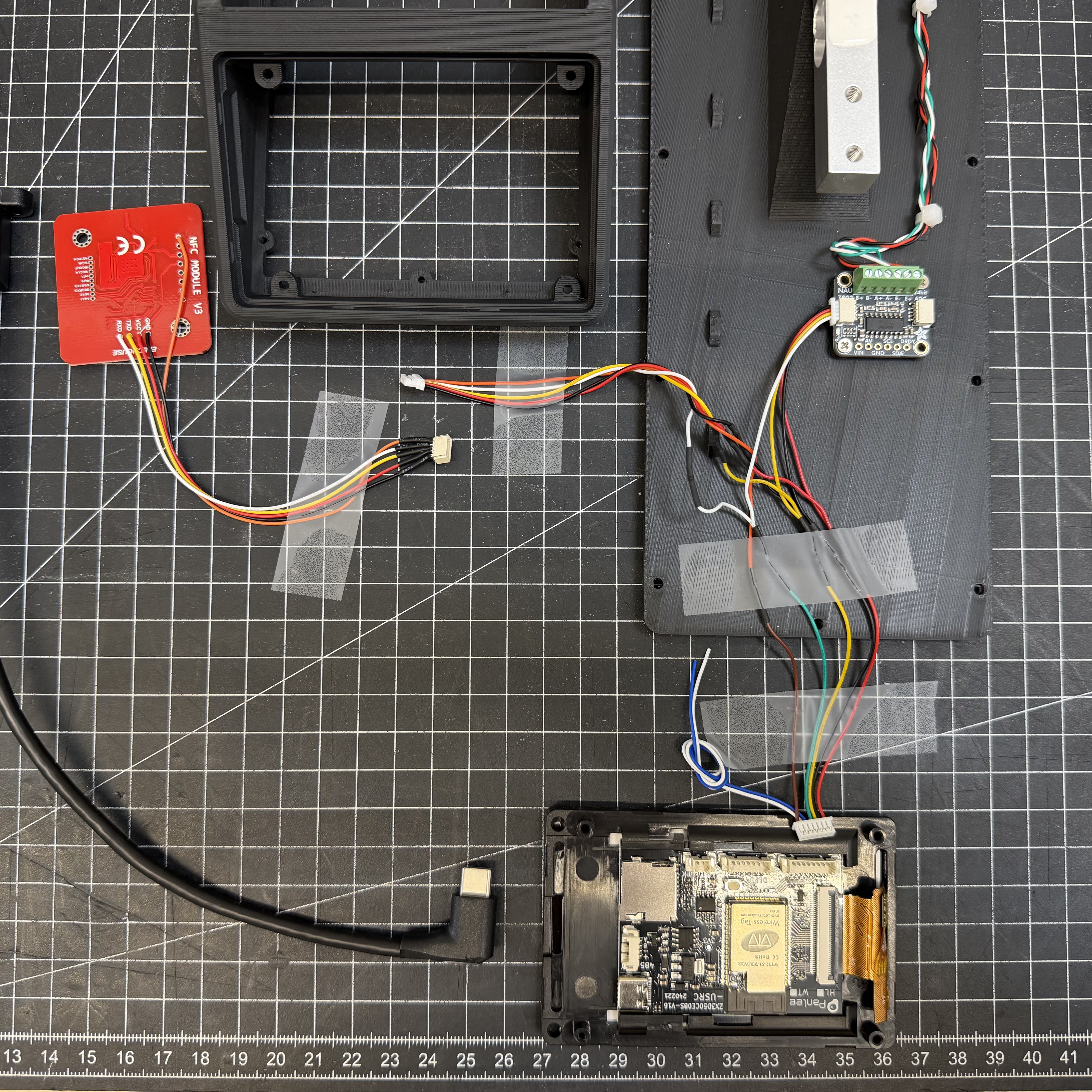
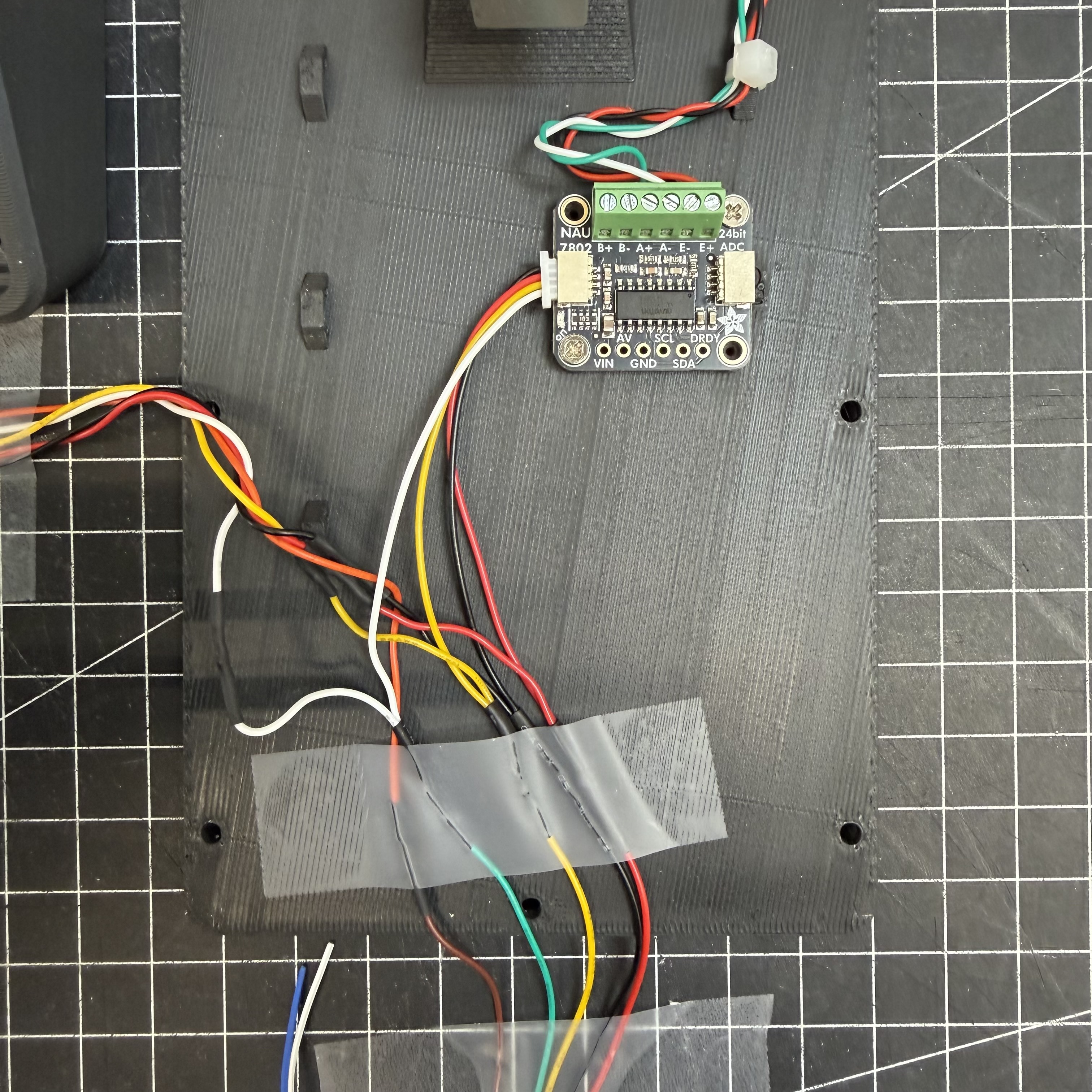
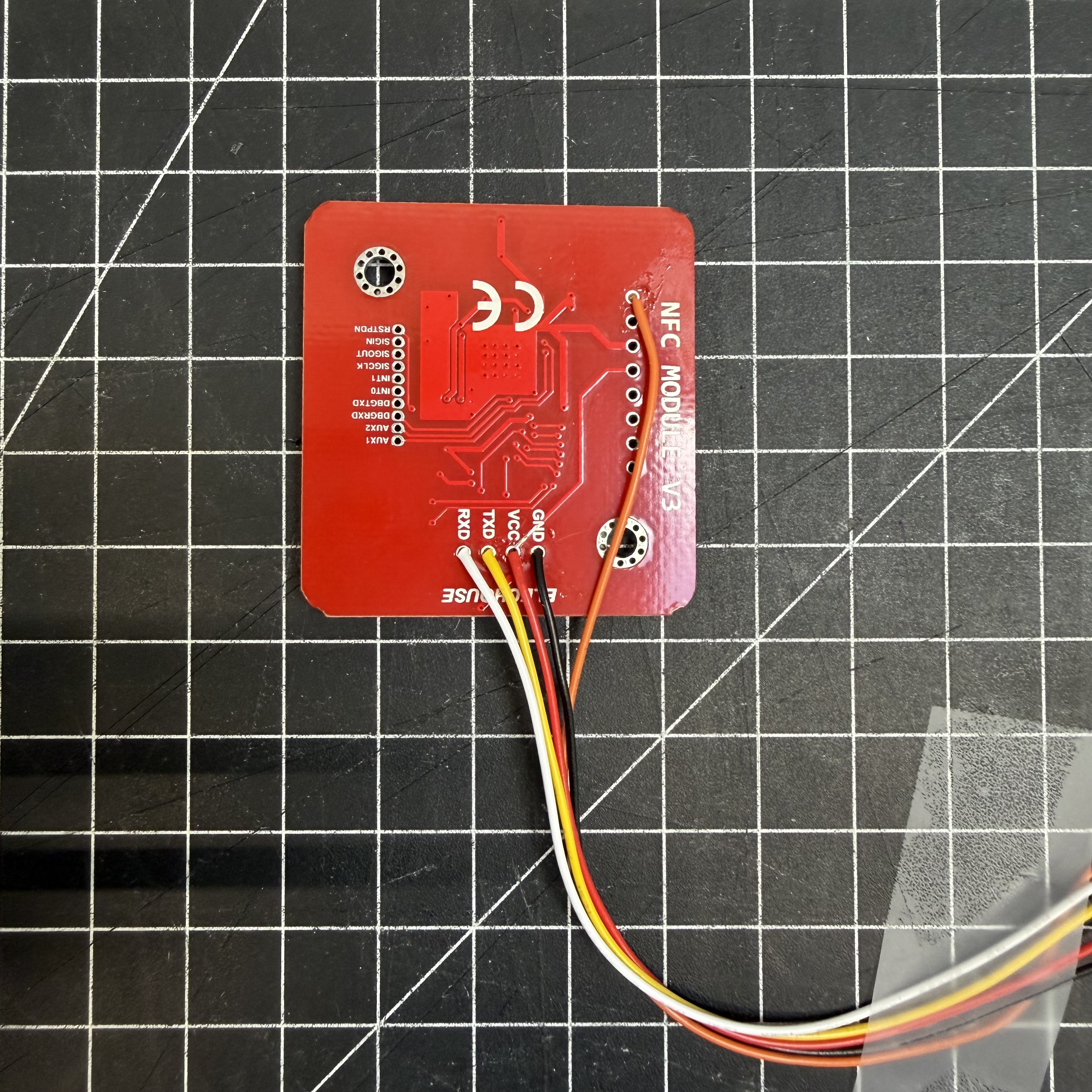
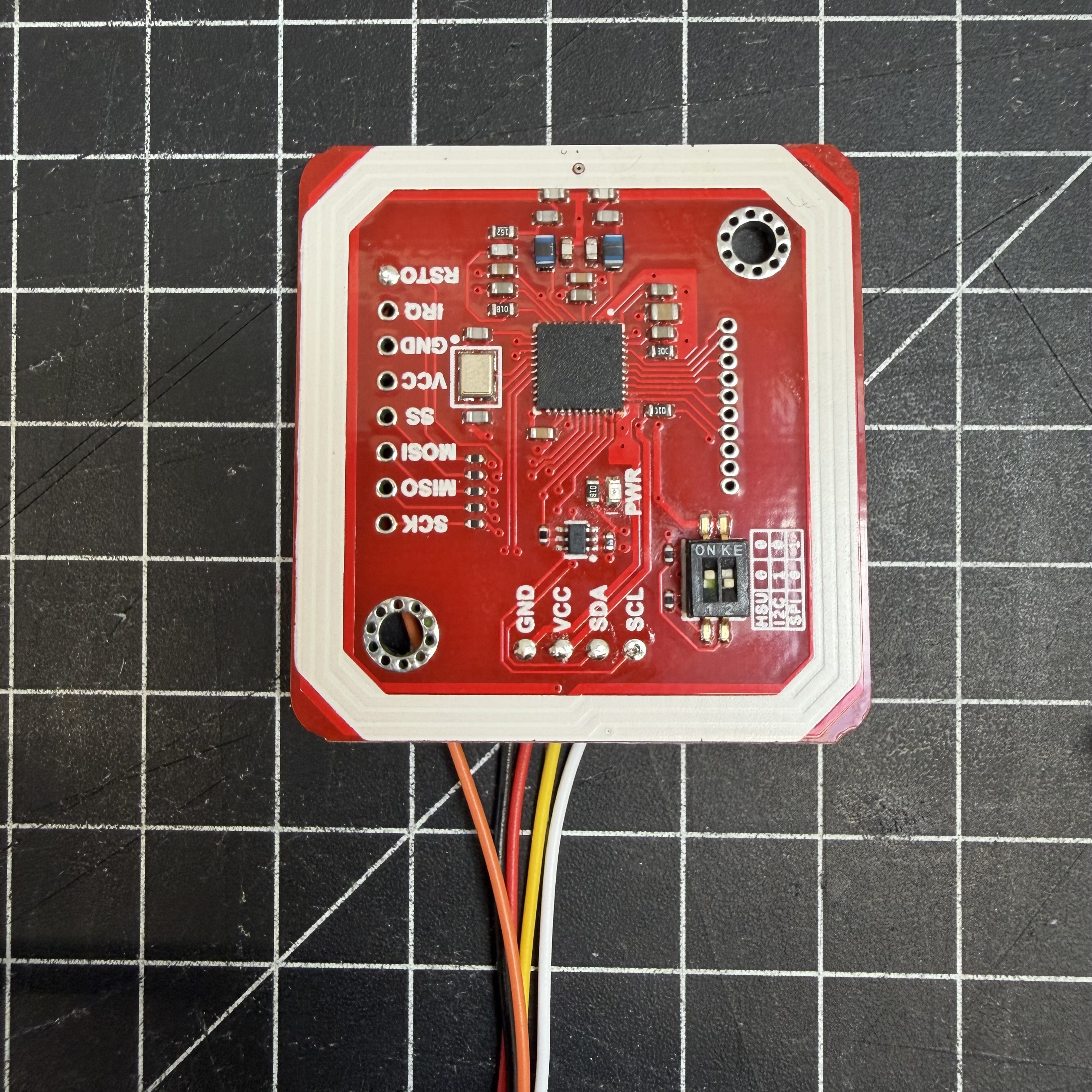
Wiring Photos:
Next Step
➡️ Assembly