Assembly
Beta build guide
If something is unclear or doesn't fit your hardware batch, please report it on Discord or MakerWorld.
Before you start
Print the enclosure first - see Printing the case.
Screws & Hardware
| Screw | Qty | Use |
|---|---|---|
| M5×25 socket head | 2 | - |
| M4×15 socket head | 2 | - |
| M2.5×5 self-tapping | 9 | Main enclosure |
| M2×4.4 self-tapping | 2–4 | Small parts |
Self-tapping screws are recommended, but standard machine screws (M2.5×5, M2×4) will likely work too.
Assembly Steps
Step 1 - Flash first
Before assembling anything, flash the firmware to the bare board via the Web Flasher. This confirms the board is working before you start wiring.
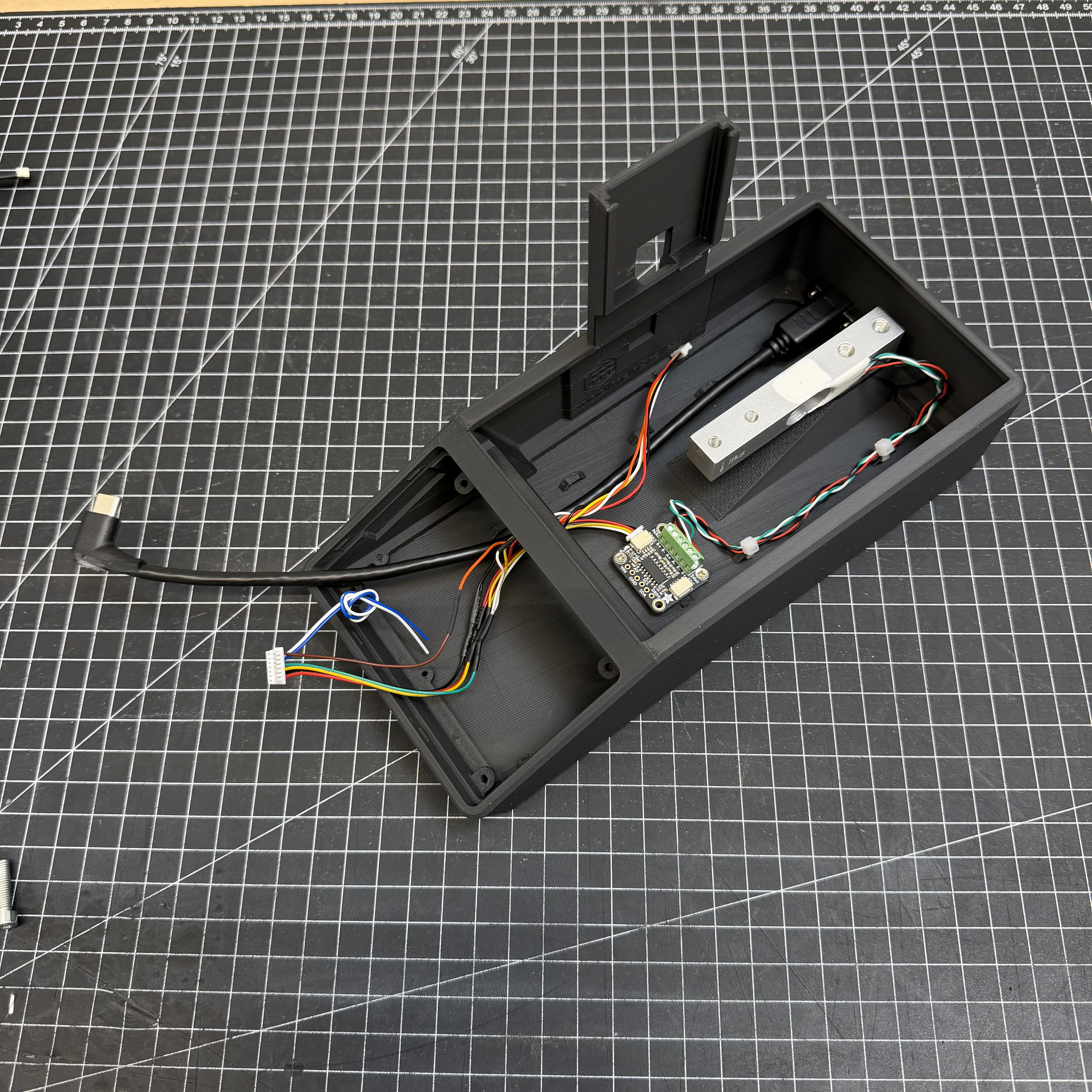
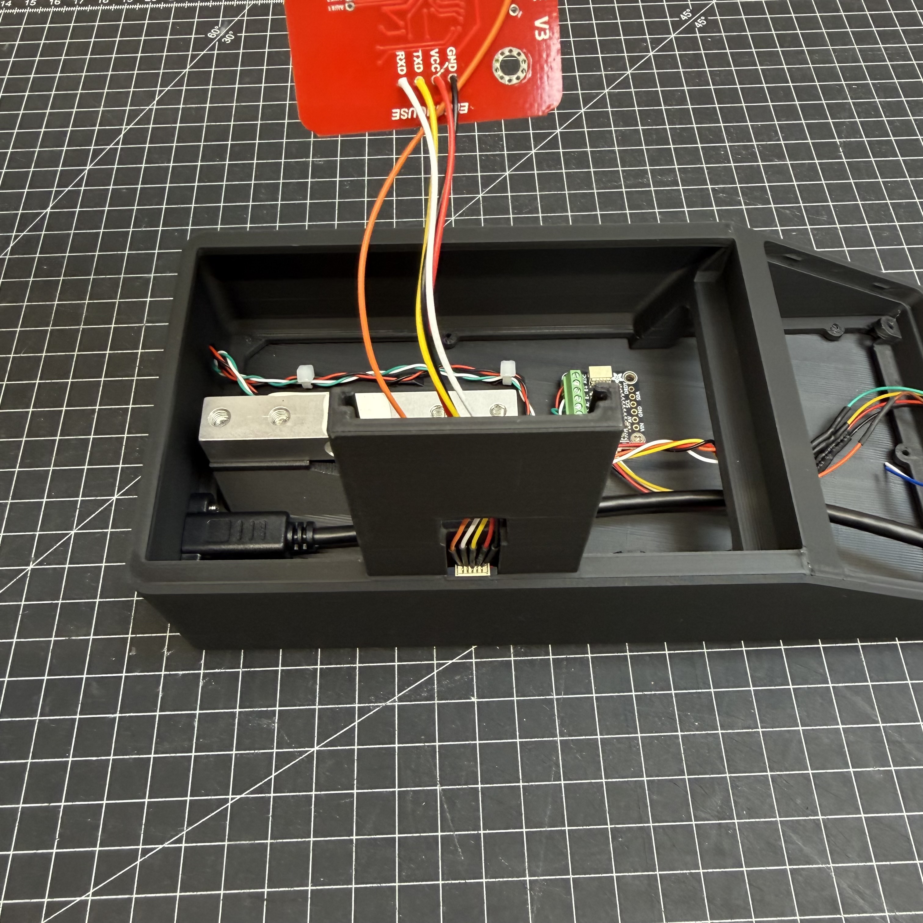
Step 2 - Wire one component at a time
Connect components one at a time and verify each one works before moving on - much easier to debug at this stage than inside a fully assembled enclosure.
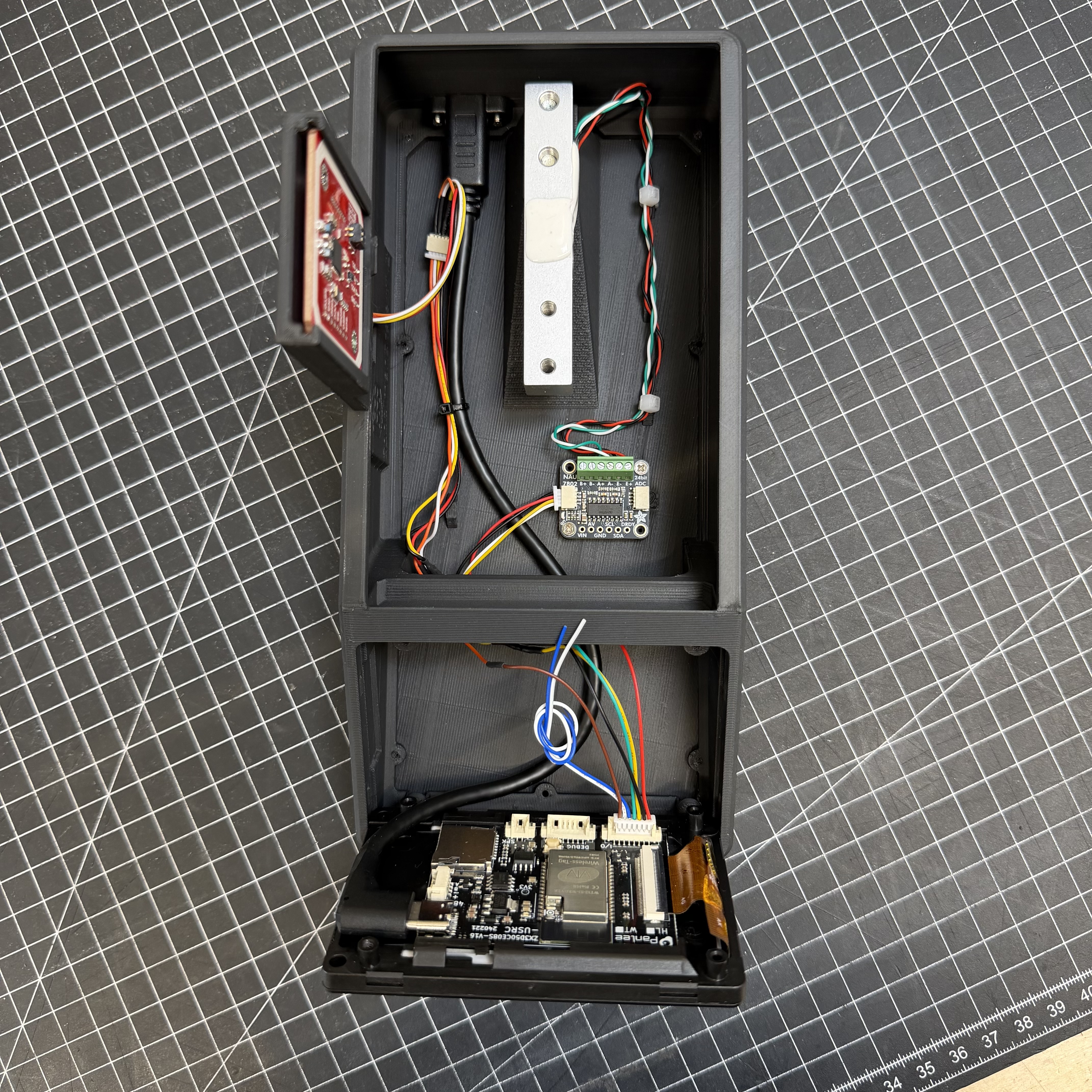
Order: 1. PN532 NFC reader 2. NAU7802 scale ADC + load cell
See Wiring for all connections.
Step 3 - USB-C Panel Mount
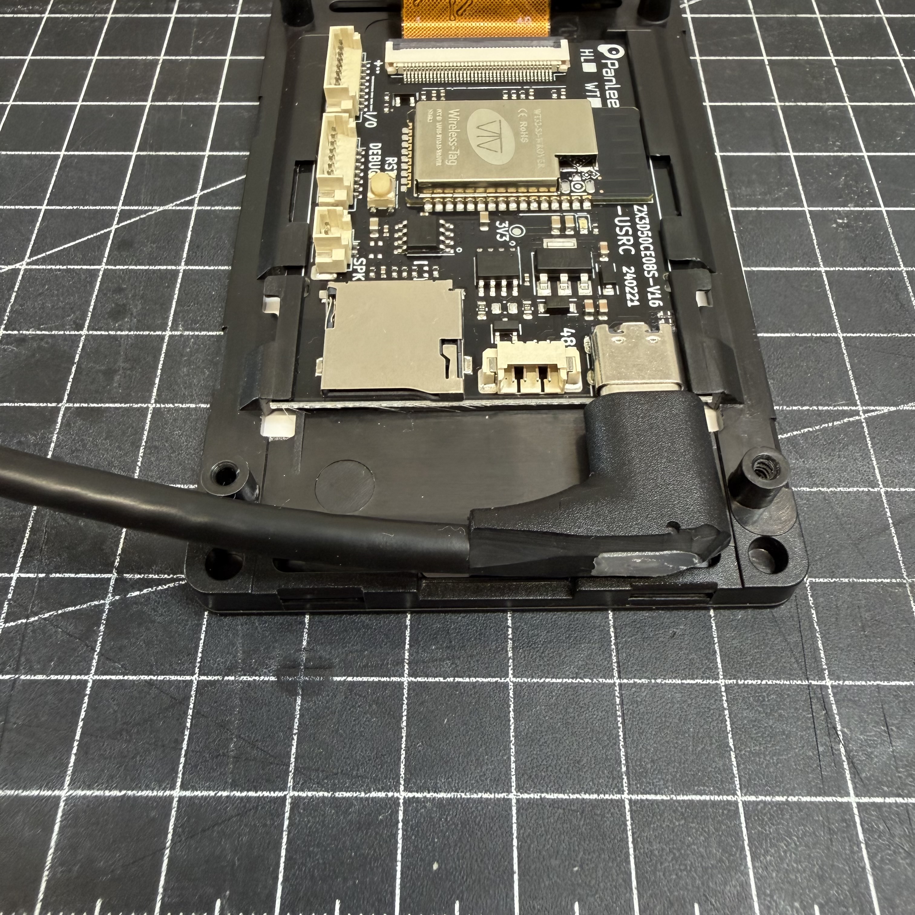
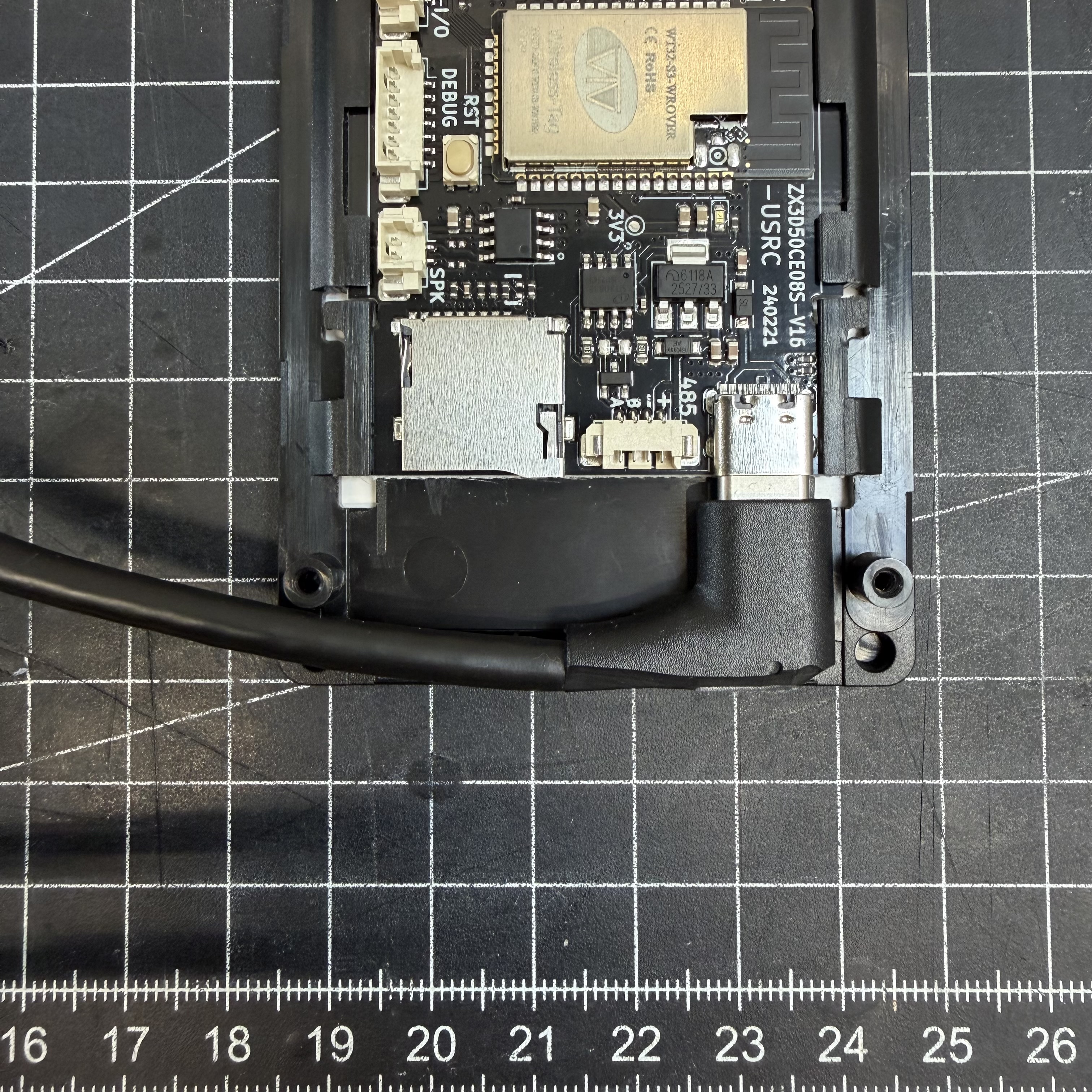
The USB-C panel mount needs to be trimmed before installation. Using a utility knife, carefully shorten the connector housing little by little until it no longer protrudes beyond the display edge. Take your time - small cuts at a time. Once flush, it fits cleanly into the enclosure.
Step 4 - Close up
Do a final check that all components are working, then press the display into the enclosure. It should sit snugly without screws. If you want extra security, it can be fastened from the back.
Step 5 - Calibrate
Carry on with Flashing & first setup, where calibration is covered step by step.
Assembly Photos